Information
Cell phone charging cable structure and technology trends
Release time: 2025-02-28
1. Basic Structure and Power Adaptability
The core structure of mobile charging cables consists of three parts: conductor, insulation layer, and outer sheath.
The conductor usually uses multi-strand twisted copper wire, with a diameter range of0.08-0.12mm, and a cross-sectional area of 0.1-0.5mm². The conductivity of copper (5.71×10⁷ S/m) and cost advantages make it the mainstream choice, while high-end charging cables use tinned copper or silver alloys to enhance oxidation resistance.
Power Carrying Capacityis directly related to cable specifications:
- 5W (5V/1A): requires a cross-sectional area of more than 0.2mm²
- 24W (12V/2A): requires a cross-sectional area of more than 0.30mm²
- 120W (24V/5A): requires 0.5mm² conductor + low impedance design
- 240W (USB PD 3.1): must reach 1.5mm² + double shielding
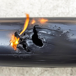
The insulation layer material is mostly PVC (dielectric strength 15-20kV/mm) or TPE (temperature resistance -40℃~90℃), and high-power charging cables use TPEE to increase temperature resistance to 125℃. The outer sheath thickness is usually between 0.5-1.0mm, and it must pass a 5kg tensile test and a 750℃ flame retardant test.
2. Enhanced Structural Design
Fast charging cables generally increase:
- Aluminum foil shielding layer: thickness: 0.025-0.05mm, reducing electromagnetic interference (EMI) to below 30dB
- Nylon tensile fibers: diameter: 250D, tensile strength 3kgf, making the cable tensile strength exceed 100N
- The outermost braided mesh:48 strandsof polyester yarn woven, enhancing bending resistance by 200%.
3. Technical Challenges of High Power Charging
In 2024, mobile phone sales have exceeded 100 million units, which poses the following requirements for mobile charging cables:
- Voltage Rating: from: 24V to 48V, requiring an increase in insulation layer thickness.
- Temperature Rise Management:During 120W transmission, the cable surface temperature must be controlled within 40℃, requiring the addition of a thermal conductive silicone layer.
- Data Transmission:The USB3.1 specification requires 2.4GHz high-frequency signal transmission, and the cable structure precision must reach 0.01mm..
4. Comparison of Outer Sheath Material Performance
|
Material Type |
Hardness (Shore A) |
Temperature Range |
Environmental Friendliness |
Application Scenarios |
|
PVC |
80-95 |
-10~70℃ |
Halogenated |
Low-end charging cables, data cables |
|
TPE |
60-80 |
-40~90℃ |
Recyclable |
Car charging cables |
|
Silicone Rubber |
40-60 |
-40~200℃ |
Non-toxic |
Mainstream fast charging, industrial equipment |
|
Braided Polyester |
- |
-40~200℃ |
Biodegradable |
Outdoor equipment, electronic peripherals |
5. Cutting-edge Technical Directions
- Material Revolution: Graphene wires (resistivity1×10⁻⁶Ω·cm) can increase the current carrying capacity by five times.
- Structural Innovation: Coaxial twisted structure: During 240W transmission, the wire diameter is reduced to 4.0mm.
Industry data shows that,the global fast charging cable market size reached 7.8 billion USD in 2023, with a compound growth rate of 12.4%. With the popularization of wide bandgap semiconductors such as SiC, it is expected to achieve 500W (10A/50V) fast charging by 2025.
 oversea@hichain.com.cn
 +8617328576881


